
Data Modeling for Graph Databases: Nodes, Edges, and Relationships in Action
Last updated on Aug 4, 2026
For many years, relational database management systems were the conformist basis for organizing enterprise data. Relational data structures, with their regulations regarding rows, columns, primary and foreign keys, as well as normalization principles, were known to be a reliable solution for the assurance of transactional data integrity and avoidance of data anomalies. Nevertheless, over the years, data has changed significantly in accordance with the development of software applications. Nowadays, modern applications, including such applications as social networks, real-time fraud detection, e-commerce recommendation systems, MDM tools, and supply chain networks, are determined not only by the isolated units of data they keep but also by how sophisticated and advanced their interrelations are.
A question that covers multiple interrelated entities in a classical relational setup often leads to the need for performing recursive joins across many databases. As queries grow longer and more complex, query speed suffers greatly due to the need to scan through primary and foreign key indexes and to calculate joins as the queries are processed. Graph databases, however, reverse the model altogether. Rather than being required to infer relationships during the query, graph databases store all relational data in a single database on the disk.
In this manual, you’ll find detailed information on various structures, ideas, designs, and processes that have to be utilized when creating efficient data models through the Labeled Property Graph system rather than conventional DB tables and traditional codes. In case you want to acquire profound knowledge of the given principles, you might want to take a complete data modeling course, where both relational and graph architecture are studied.
The Change in Perspectives: Movement from RDBMS to Graphs
In order to create more successful data models in graph databases, data engineers and data architects need to forget about many of their principles developed over many years of experience of creating models in relational systems.
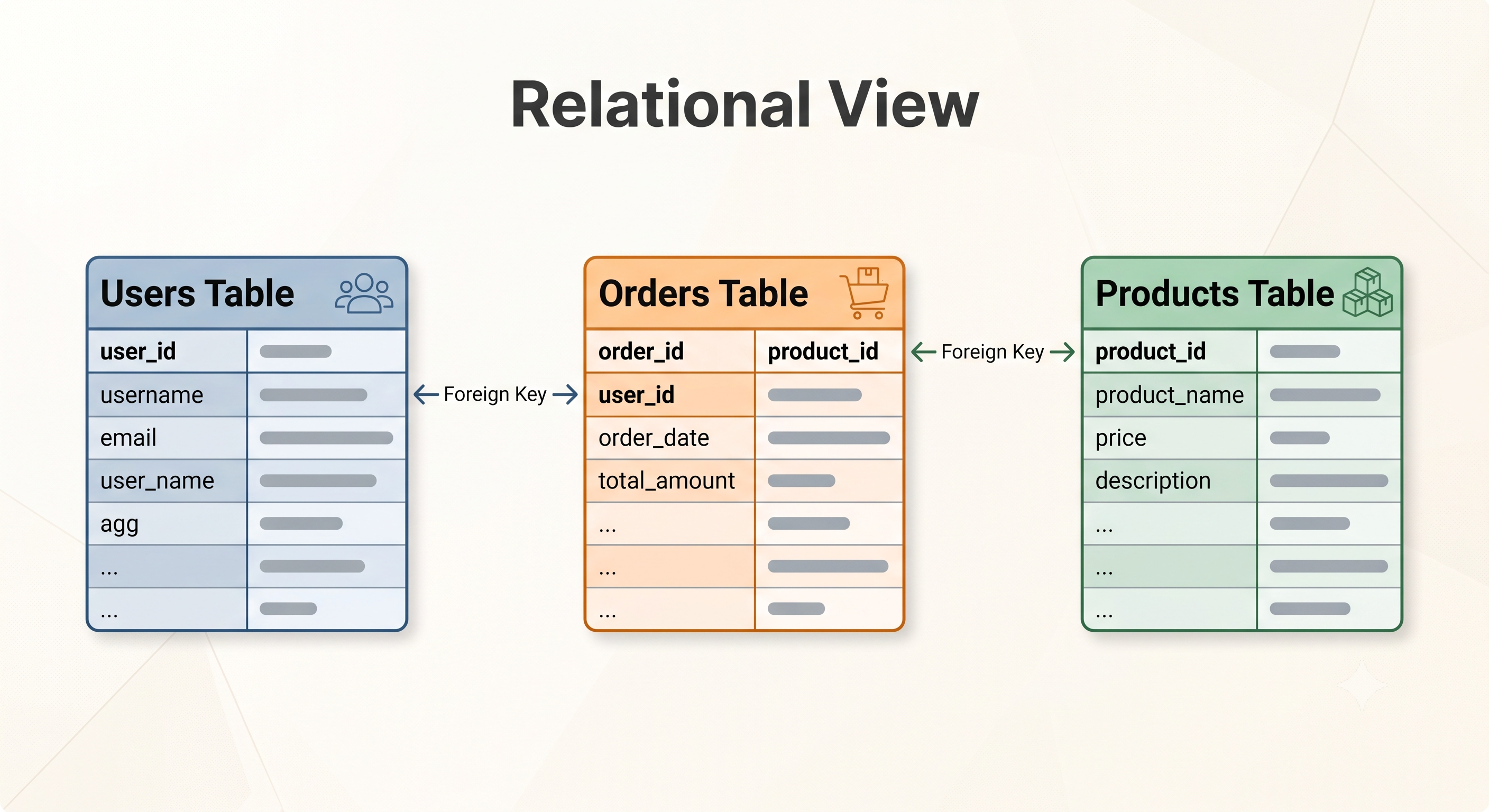
In a relational database, the goal of data design is to separate all objects into multiple normalized tables as much as possible to avoid redundancy. There is no explicit reference to relationships: they are indicated only by the fact that the values obtained through foreign keys are the same. When a system needs to find out how two objects are correlated through three or four objects, the relational mechanism has to carry out multiple index lookups from multiple intermediary tables. In other words, in mathematics terms, multiple hops in relational systems require a huge amount of time depending on the depth of the search. As a result, a traditional join query becomes very inefficient when the size of the global database grows to tens or hundreds of millions of records.
By using Index-Free Adjacency in its architecture, graph databases bypass this restriction of structure. In an actual graph storage engine every single node has pointers to its neighboring nodes in the memory. There is no need to search for a value in a global index or perform a join operation every time a relationship must be traversed. The engine simply follows the pointer, which may be either in the memory or disk, to the node.
Since the traversal does not involve any lookup operation, the speed of queries is solely determined by the size of the subgraph being traversed. A query requiring three hops on the graph with billions of nodes will take the same amount of time as the same query on a graph with a few thousand nodes. Thus, instead of asking questions of how data can be organized in the form of tables of data, the modeling task is to design a meaningful network of nodes and their relationships, taking into account the need for the paths of travel to be as short as possible.
Constitutive Elements of the Labeled Property Graph Model
While there are different mathematical concepts available to work on different graph structures like RDF triples which are widely used in semantic web applications, it is important to note that the Labeled Property Graph model has become the leading working standard in its field of modern enterprise graph engineering.
The framework of Labeled Property Graph consists of four basic components that are closely interconnected: Nodes, Labels, Edges, and Properties.
Nodes (Vertices)
Nodes are the main independent units in the business domain. Each node serves as a “noun” in the data network. Thus, entities like particular consumers, products, bank accounts, places, electronic devices, or transactions can be presented by various nodes. Nodes exist separately in the database and serve as connection points for properties and edges.
Categories Tags
A label is one of the ways of tagging a node on a higher level, defining the role of the node through labeling. A label is like a category tag that classifies nodes into different function-specific groups. For instance, a node representing a specific customer may be tagged as Customer while a different node representing the admin user will have both User and Admin tags. The use of labels is extremely important when it comes to enhancing queries since they act as the starting points of nodes that are indexed by the graph engine during query execution.
Links (Edges)
Edges are used to represent explicit semantic relations between two distinct nodes. Edges are verbs in graph theory that describe the interactions and relationships between entities. The edges are highly structured as compared to the indirect relationship in relational databases.
The definition of edges indicates a strict relationship between source and target nodes. Each edge should have a relationship type like PURCHASED, MANAGES, LOCATED_IN, and CONNECTED_TO.
The edges can be traversed both in outgoing and incoming direction. In addition, there are no variations in terms of algorithmic performance.
Properties
Properties are pairs consisting of a key and a value that can be assigned to both edges and nodes. In the case of a node, properties refer to the characteristics of the object, e.g. a username, e-mail address, creation date. With respect to an edge, properties refer to how the relationships have been qualified, quantified, or described. For instance, an edge of type PURCHASED linking the Customer node and the Product node will carry properties like time of transaction, quantity purchased, or discount rate offered. Thus, the connection of any edge with extra information makes the relationship more than a mere link.
Query-Driven Design Methodology
Traditional relational modeling goes through an inside-out process. The developers first analyze the business domain and figure out the core entities of the business and normalize them into tables by utilizing separate tables according to the Third Normal Form. Later, they define the constraints before forming any queries on the application.
Through graph modeling, the flow in question is reversed due to the use of query-driven techniques. The graph models are structured to make the most of their ability to traverse and navigate through various paths. Understanding these advanced methodologies is essential for those applying for formal data modeling certification programs to prove their enterprise-level data designing skills.
The Four Stages of Graph Modeling Process
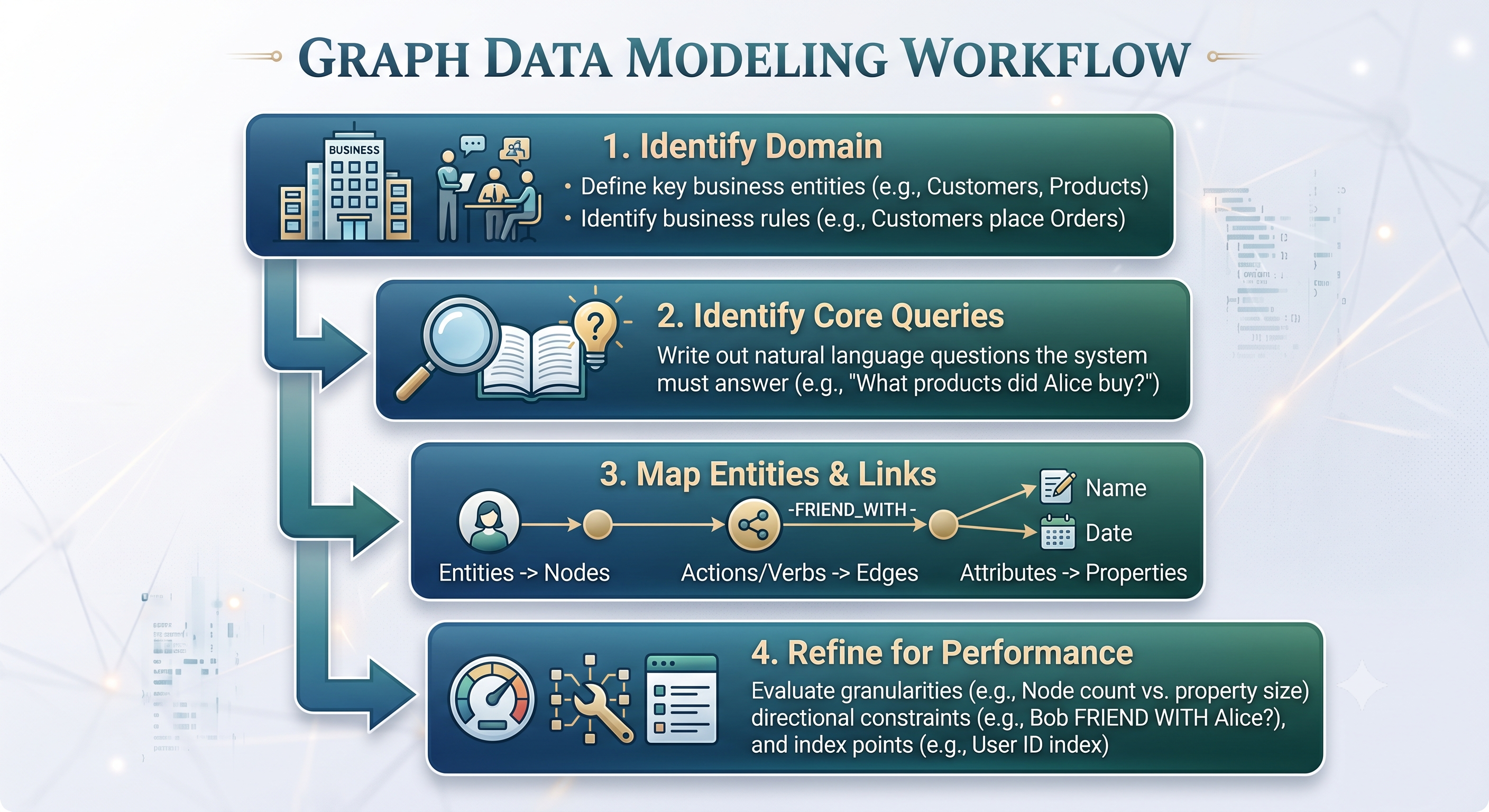
The creation of a good graph model has a clear four-step engineering cycle:
Domain Question Mapping: The first step is to compile a list of all important business questions the application should answer in real time. All questions should be formulated in a natural language. For example: What products have been purchased by the friends of a given customer who have not purchased that product yet? Or: Has the bank account ever dealt with any fraudulent entity within the four degrees of separation?
Identification of Nouns and Verbs: Use grammar parsing to analyze the questions in your area of expertise. Recognize the key nouns, which are the Nodes candidates. Identify the verbs and the actions that any representatives of these nouns can perform; this means that it is the Edges.
Schema Mapping: Create a scheme showing relationships between elements and their types. Identify the beginning labels, establish the edge’s flow and answer the question what attributes belong to Nodes and what attributes belong to Edges.
Traversal Optimization: Compare the received schema with execution requirements. Change the details, create hierarchical ways and find out whether the most frequent paths require special types of relationships or shortcut Edges.
Advanced Architectures for Modelling Graphs and Decision Making
In order to create effective models of graphs to cater to the needs of an enterprise, some architectural considerations need to be made. Such design considerations are emphasized in data modelling courses, so that the flexibility of the model is maintained.
The Node versus Attribute Decision Framework
One of the adult challenges in graph modeling is determining if a specific set of attributes should be held as a property inside the relevant node or become a separate node linked with the help of relations.
Take a simple property like the country of residence of a user, for example. You could save the string directly as a property of the User node or create a new country node and link it with the User node through the related location relation.
To make the right architectural decision, consider the way in which the information is going to be retrieved:
When to Treat as Property: The property must be characteristic of that entity (like telephone numbers, social security numbers, etc.), and it must not have a possibility of being used as a pivot point leading to other entities, and must not need any separate metadata.
When to Elevate to Independent Node: The property must have a value that many entities (thousands or millions) share (like job title, skills, city, or IP address), and if your program often needs to hop over that property in order to discover related communities’ or behavior. Elevating common values to nodes makes it a valuable structure for the data world.
Specific Types of Relationship vs. General Edges With Properties
When it comes to modeling the security permissions/access control systems, the architects must make the choice of either using generic edges with properties, or specialized edges.
For instance, the access permissions can be modeled using a generic edge HAS_ACCESS that contains a property indicating whether access is read/write/administrative. On the other hand, the model can use specific edges CAN_READ, CAN_WRITE, and CAN_ADMINISTER.
When it comes to high-performing applications, employing edge types that specialize is significantly better than using a general-purpose edge type that must be filtered by properties. Graph traversals can filter the edges internally and at the pointer level of the hardware before getting to the properties. Checking the properties of thousands of general edges creates an unnecessary load during the process of dynamic traversal.
Intermediate Event Nodes
In a standard property graph, edges connect exactly two nodes. However, in many cases of real-life events, there are more than two actors involved. For example, consider a situation at a store where a customer is buying some product from a salesperson, in some particular outlet with a specific promotion.
The solution is to connect all these entities through a network of pairwise cross-edges that creates a kind of confusion in the structure and querying of the events. The way out is to introduce Intermediate Event Nodes (also widely called hyperedges).
Instead of making connections from all entities involved in the transaction, one should introduce a main central node representing the Transaction. After that, draw connections from this central node of the Transaction to the involved Customer, Product, Representative, Store, and Coupon. This not only separates the event but also provides an opportunity to include details like the time of the event happening and the total cost.
Modeling of the temporal history and changing states
Even though in a graph query the traversal is based on edge paths, changing state needs to be designed properly. For instance, if the user changes their home address, simply changing the properties of the Address node or changing a location edge gives no historical context to the event.
Dated Edge Logging: Maintain the simplicity of relations by creating more edges based on that same concept between two nodes, however, distinguishing them with different dwelling and birth times which are included into edge properties.
State Version Chains: In cases of complicated switching of states, individual states are transformed into specific nodes which hold states along the timeline with the help of transition edges. The current state node is connected directly to the entity with the help of an active state link while the previous states are in the back of the linked node in order to perform the audits.
Real-World Examples
Understanding the advantages of the graph architecture is possible only through looking at real incidents related to the daily usage of the graphs.
Example 1. E-commerce real-time recommendation engines
Whenever peak shopper volumes are encountered, conventional e-commerce systems fall short of providing sub-second customized suggestions. When managing a relational database, the co-occurrence of products (i.e., computing what products were purchased by consumers who viewed or purchased the given product) necessitates running enormous aggregation queries on hundreds of millions of sales data rows.
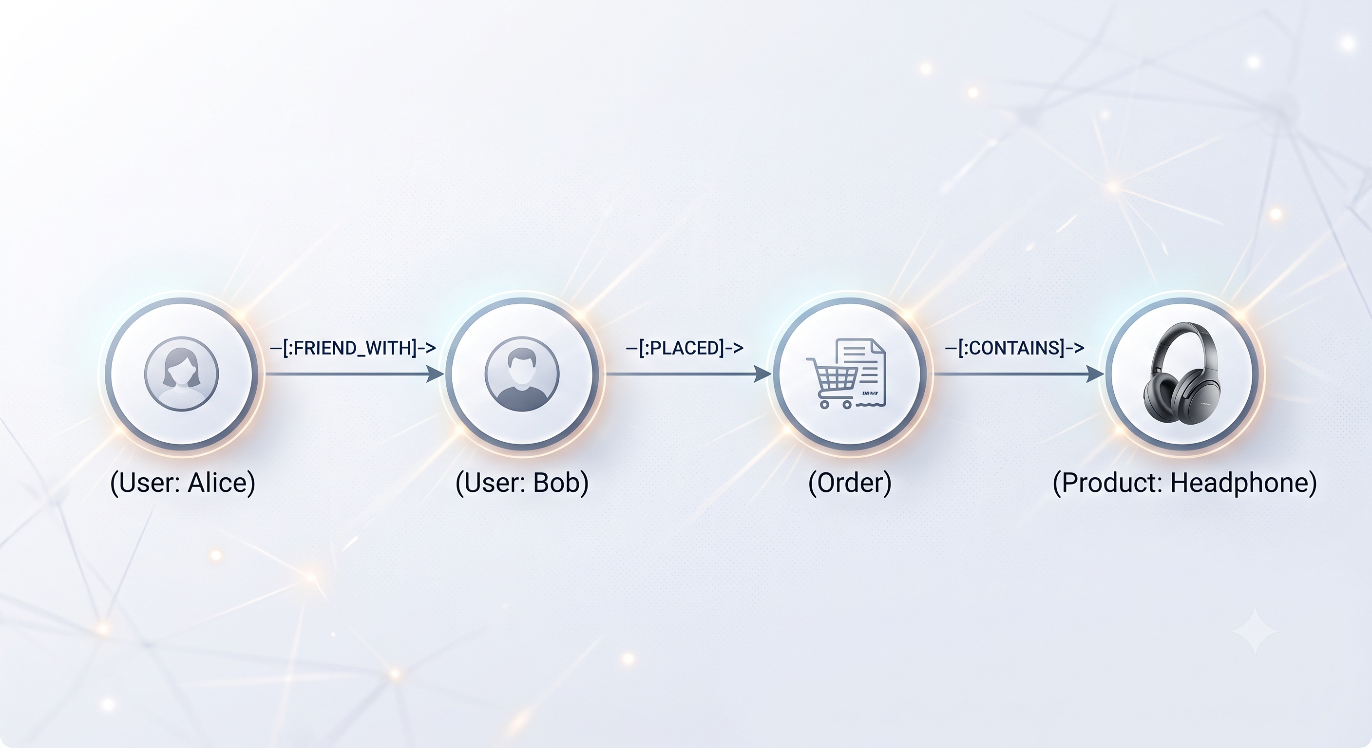
In a graph model, product recommendation is performed through localized path traversal. In this case, the graph schema is composed of Customer nodes linked via edges labeled BOUGHT to Product nodes, which are in turn connected to nodes labeled Category.
Whenever a user accesses a product page, the recommendation traversal process is initiated at the particular Product node. The graph engine backtracks along the incoming BOUGHT edges to collect Customer nodes who have purchased that product. Immediately after this step, it moves forward following outgoing BOUGHT edges, determining Product nodes neighboring the Customer nodes, excluding the ones which have been acquired by the user.
Since this query makes use of only the nearby connections of the item, the traversal goes through only a particular part of the overall graph. This computation is finalized within a few milliseconds, offering ultra-relevant products to the user instantly, irrespective of the size of the whole history of transactions.
Case Study 2: Identity Resolution and Financial Fraud Ring Detection.
Criminals have developed synthetic identities and are now successfully utilizing these against traditional automated detection systems. A single fraud ring might be able to register dozens of unrelated user accounts that rely on the same piece of personal information, for instance, having a common physical address for five accounts, using the same phone number for several others after which the logins would come from shared hardware footprint.
Relational databases utilize heavy self-joins across massive non-related tables with accounts, devices, phone numbers, addresses, and credit cards in order to extract and identify the connected account networks. In the event that the required degree of connection exceeds the second one, query execution time becomes prohibitively large, negating all real-time fraud prevention efforts.
The model of identity resolution that is contingent on graphs helps to solve this problem by turning all characteristics of common identities into well-defined nodes. Technical accounts, cellular numbers, identifiers of a device, physical addresses, and bank cards exist as separate nodes with specific edges, representing the links between them.
When any account is suspected of fraud, security algorithms do not have to examine worldwide tables. The model begins to search for connections from the flagged account node along edges of common identity up to four steps away. Then all active accounts that were found in the web made as a result of this local search are regarded as high-risk members, which allows financial institutions to block automatic transactions beforehand.
Key Structural Anti-Patterns
Creating efficient graph structures necessitates staying clear of certain design pitfalls as these can compromise traversal efficiency and lead to high memory consumption.
The Supernode Problem
The supernode refers to a situation where a graph node has tens of thousands or even millions of inward or outward edges. An instance of the Supernode problem would be when a single node describes a country and is connected by millions of User nodes linked to it via LIVES_IN edges.
When a traversal query passes through a supernode, the traversal logic has to analyze millions of edges in order to identify outgoing edges, making the benefits of localized traversal redundant.
The concept of diminishing the impact of supernodes can be followed in the below ways:
Avoiding connecting such nodes to not very selective static nodes is a good practice. In case of very high-cardinality and non-selective attributes like, even the attribute can be kept as a normal string in a node instead of being promoted to an independent node.
As an alternative, intermediate organization hierarchies can be created. For example, instead of directly connecting millions of users to a single Country node, an intermediary regional structure such as State, District, and ZipCode nodes can be created.
Using Arrays for Modeling Foreign Keys
Often developers who are moving from document and relational stores tend to create a list of foreign identifiers in node properties. For instance, a User node may contain a string property with an array of identifiers of friend users.
This kind of modeling compromises Index-Free Adjacency, since for finding friends of a user the engine has to read the string-array, parse it, and use the secondary indexing. Thus, it is always better to use native explicit edges between separate nodes for making connections.
Error of Relationship Type Explosion
Another frequent type of modeling mistake is adding temporal or state information directly into the name of the relationship type, e.g., creating different relationship types for PURCHASED_IN_2024, PURCHASED_IN_2025 and PURCHASED_IN_2026.
This approach leads to pollution of the database structure catalog, imposes considerable difficulties in writing dynamic traversal paths and hampers schema evolution. Therefore, it is crucial to stick to clean and uniform naming of relationship types and model state changes or time indicators as edge properties or connected states in the database.
The Unnecessary Bi-Directional Edges
Due to the fact that property graph edges have a clear direction, newbies tend to mistakenly create two redundant edges going in two opposite directions between the same pair of nodes to make sure that there is always a path available for the queries to go back and forth.
This approach does not only increase the volume of memory required to store the relationships but also does not provide any practical benefit. The modern architectures of graph DBMS often take advantage of the directional properties of edges while performing queries and offer the ability to disregard directions in the process of executing queries whenever this is required, according to business logic.
Conclusion and Check List for Architectural Design
Graph databases provide efficient tools to model complicated, connected business questions. They give a chance to shift from classic relation tables to nodes and direct connections with relevant properties, allowing for real-time multi-hop real-time analytics that were unavailable before.
In advance of utilizing a graph model, its design must be evaluated as per the above-mentioned principles. Organizations seeking to enhance the knowledge of their engineers in such patterns should undertake data modeling training, which provides them with practical experience in creating scalable and flexible systems for the future.
Query Matching: Is the data of the key nodes and traversal paths received from the key queries of the application?
Clarity of Expression: Can your nodes demonstrate main nouns of the domain, your edges show actions or verbs, and your properties provide important descriptive information?
Default Starting Points: Are your entity labels clearly defined in ways that the entry queries can immediately locate the first candidate nodes without going through a complete graph search?
Supernode Avoidance: Have you identified and mitigated any potential supernode using either property retention or structural domain hierarchies?
Normal Connections: Are the relationship edges described as normal directed edges rather than being embedded or defined as array properties?
These three patterns provide a foundation to build the scalable, expressive and future-proof system models able to enable unlocking the real value behind complex enterprise networks.